How to Assemble an Airsoft Mp5
How to Assemble an Airsoft Mp5
Wiki


How To Detach a MP5 Airsoft Submachine Gun
The Heckler & Koch MP5 is an iconic submachine gun in the entertainment world. Most everyone have seen it in one case in a moving picture. And it's natural option for someone who is getting into airsoft. But it's disassembly is non the easiest compared to an airsoft M4. In this commodity, nosotros show you how to disassemble the various parts of an airsoft MP5.
Comments & Discussion >>
Shoulder Stock
The MP5 shoulder stock is the easiest component to remove on the gun. In fact, information technology'southward easier to remove than a M4 shoulder stock. There are various types of MP5 shoulder stocks. But the removal process are the same. In this commodity, we evidence yous how to remove a collapsible shoulder stock, which is the hardest MP5 shoulder stock to remove. Therefore, you will exist able to apply this process to any MP5 shoulder stock.
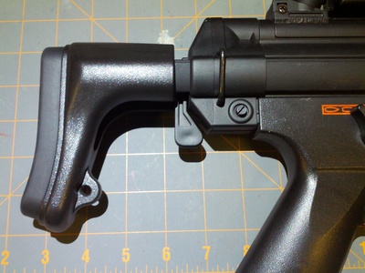
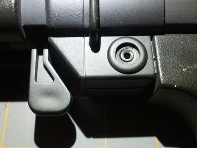
The photograph above shows the MP5 collapsible shoulder stock. The only thing holding it onto the receiver is a pin. The pin is held in identify by the flat-screw next to the sling mount. After you unscrew it, you can tap the pin (see photo below) out.
Next, pull the shoulder stock straight dorsum to separate it from the MP5 receiver (see photo below). This is nearly as far as you accept to go on whatever other MP5 shoulder stock. At that place are a few more than steps for the collapsible version.
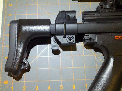
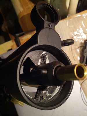
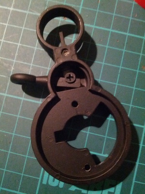
The collapsible shoulder stock guide(s) are held onto the receiver by a lock. You have to raise the guides slightly to clear the lock as you slide information technology out completely. The photo beneath shows the guide lock.
The following photo shows the guide lock components. The shinning metal component acts as a spring. The black plastic component is the lock.
Comments & Discussion >>
Wink Suppressor and Iron Sight on Non-Silenced MP5
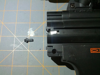
The photo below shows the front finish of a non-silenced MP5 (i.e. JG M5-J). As you tin see, the flash hider is practically glue sealed to the front end. Instead of literally breaking it off, y'all tin can really remove information technology with the iron sight.
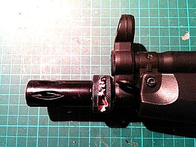
Showtime, remove the sling mountain. The sling mountain nut is on the other side as shown in the photograph below. A flat head screw driver will exist able to remove unscrew information technology.
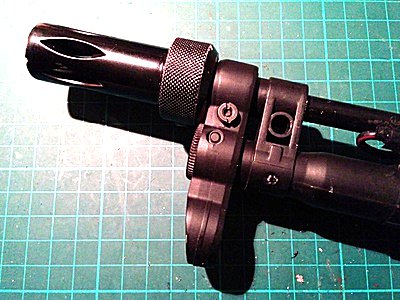
Next, use a hex wrench to loosen the hex prepare screw below the atomic number 26 sight (run across photo beneath).
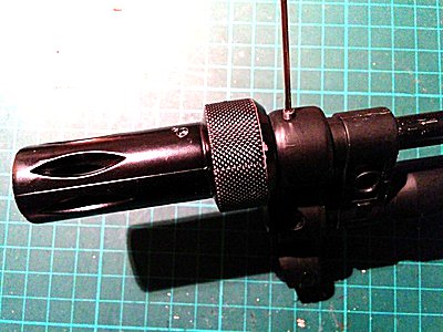
Now, it's a matter of pulling the front off the MP5. The photo below shows the flash hider and the iron sight removed as a unit.
The front flash hider is a standard MP5 quick release type. Just it'southward glued onto the muzzle tip quite solidly. In the photo in a higher place, y'all tin can encounter that the quick release latch is broken. But after some hot water boiling, the muzzle tip comes off with the flash hider quite easily as shown in the photo beneath.
You can become a replacement 14mm thread cage tip from Airsoft3D.
Comments & Discussion >>
Silencer, Iron Sight, and Hand Guard on Silenced MP5
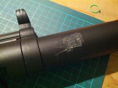
The JG M5-S6 comes with an integrate mock silencer similar to the real steel H&Grand MP5SD3. In gild to detach the residue of the gun, the mock silencer take to be removed. Nonetheless, it is glued on. Therefore, the only way to remove it is to apply a vise grip on information technology. The photo below shows the damage that volition be done to the mock silencer when it is removed in this manner.
Twist information technology a quarter plow counter-clockwise and the mock silencer tin can be removed. The photograph below shows the front end fe sight and the inner barrel after the mock silencer is removed.
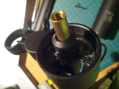
As yous can come across the inner barrel does not extend the full length of the mock silencer. Information technology'south some other reason why you'd want to disassembly this gun; to put in a longer inner barrel.
The front end fe sight is screwed downwards with two screws (see photo below). The bottom one is a machine screw. So when you put them dorsum, be sure they get to the right place.
After unscrewing them, pull the iron sight forrard to remove it (see photo beneath).
Afterwards yous've removed the front iron sight, you lot tin remove the handguard structure. There are four screws on the left side of the gun (see photo below). Removing these four screws will allow you to remove the structure to get to the outer barrel.
Comments & Give-and-take >>
Outer Barrel
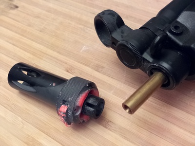
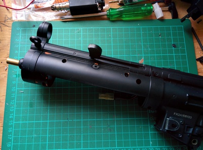
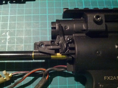
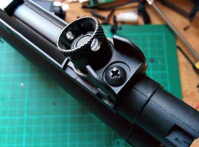
The next step is to remove the charging handle. Information technology is fastened by a machine screw to the hop-up unit of measurement (see photo below). Remove that screw and utilize the charging handle to popular itself loose.
The photograph beneath shows the hop-up unit subsequently the irresolute handle has been removed.
The photo below shows the other side of the hop-upwards unit of measurement where the nut for the machine spiral sits.
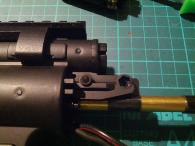
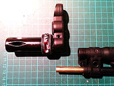
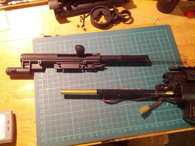
The photograph below shows the charging handle detached, then that y'all tin can now remove the outer barrel (black tube effectually the brass inner barrel).
Comments & Give-and-take >>
Motor
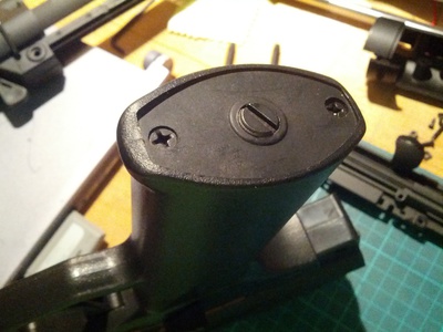
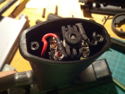
The motor is installed in the handgrip. To remove the motor, simply unscrew the bottom plate from the handgrip. It's fasten past ii Phillips screws (meet photo below). Don't turn the middle flat-head screw; that is the motor date adjustment screw. The base of operations plate is not symmetrical forepart to back. Therefore, yous should mark the forwards position with a Sharpie to save you same fourth dimension putting it back.
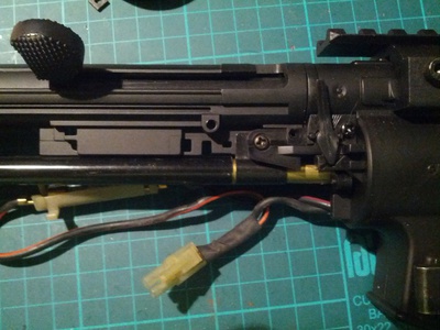
Later removing the base plate, you'll see the motor wired up to the gearbox (see photograph below). Unhook the wires and remove the motor.
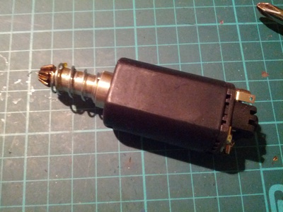
The MP5 has a long type motor (come across photo below). It's manifestly vanilla with no marker on it.
Comments & Give-and-take >>
Handgrip
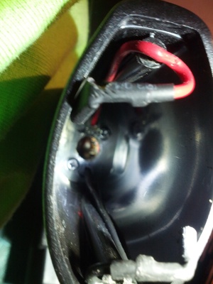
Once the motor has been removed, you tin can remove the handgrip. There are ii screws within the mitt grip that secures information technology to the gearbox (see photo below). Unscrew those two screws.
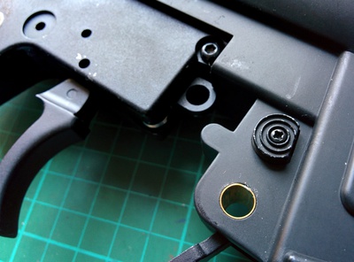
And so you lot take to remove the handgrip/receiver pin. Information technology'south right nether the magazine release push. Apply a flat head screwdriver to unscrew the pivot. Then use a punch or hex wrench to push button the pin out. The photo beneath shows the pin removed.
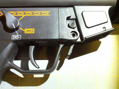
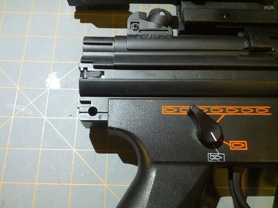
Now, you have to remove the two selector switches on the receiver to remove the handgrip. The selector switch on the left side has a tiny hex gear up screw (encounter photo below). You lot'll need a one.3mm precision hex bit to remove it.
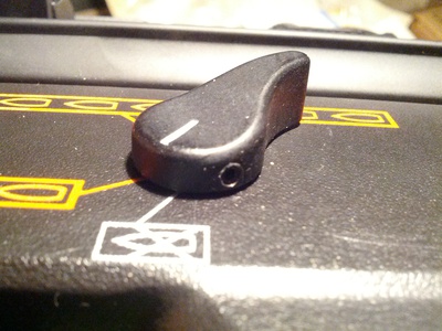
Afterwards loosening the gear up screw, pull the selector switch off. Then slide the selector switch on the right side of the receiver out too.
When both selector switches are removes, you can remove the handgrip from the receiver. There is a small selector switch plate inside the handgrip. Be careful you don't lose it.
Comments & Give-and-take >>
Receiver
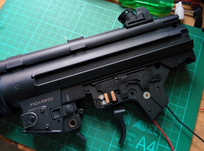
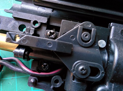
The following photo shows the black metal gearbox exposed from the receiver. To take the receiver apart, you lot'll take to remove the screw just behind the magazine release catch. And so remove the screw toward the back of the receiver, normally under the shoulder stock attachment.
Then you'll have to remove the magazine release push and take hold of. Unscrew the pocket-sized precision screw on the button (see photo beneath). Then remove the push button and the catch.
Next, you'll need to remove the rear atomic number 26 sight (see photograph below). Unscrew the top screw. Then pull the rear iron sight off the receiver.
Note the windage adjustment screw in the photograph below. Exercise not tight or loosen this screw. This adjustment screw does not affect the disassembly process.
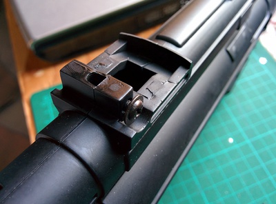
Subsequently removing the rear fe sight, yous can have the plastic receiver apart to reveal the gearbox and the hop-upward unit of measurement (run into photograph beneath).
The hop-up unit is screwed onto the receiver. That also keep the gearbox from existence removed. To remove them, y'all'll take to unscrew the two screws that are holding the hop-upwardly unit in place (see photograph below).
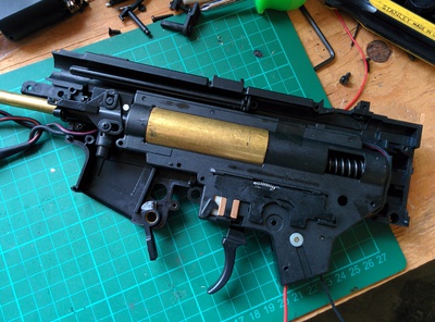
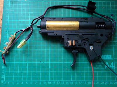
The following photo shows the version 2 gearbox that is within the JG MP5.
Comments & Discussion >>
Hop-Up Unit
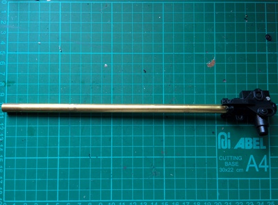
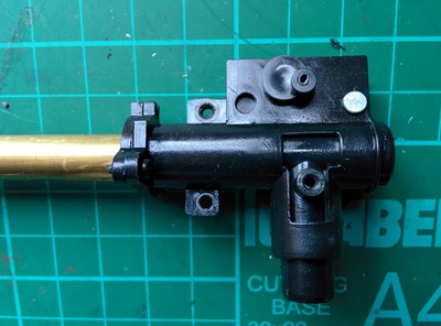
The post-obit photo shows the hop-up unit and the inner barrel removed from the receiver. In this section, we will separate these two parts.
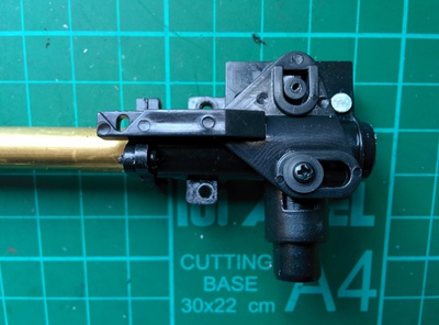
But earlier we start disassembly, let's become familiar with the MP5 hop-up unit. Photo beneath shows the hop-upward unit from the left side. The top layer is a slider the changes the hop-upwards.
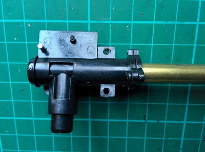
The following photo shows the hop-upwards unit from the right side.
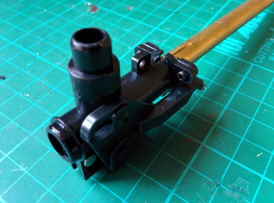
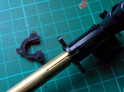
To remove the inner barrel, yous'll have to remove the front plastic fastener that keeps the inner butt in place. On this hop-upward unit, it is tied downwards past two small screws (see photo below).
It'southward easier to remove the screws on the front plastic fastener if you remove the sliding hop-up adjuster. The photo below shows the adjuster slider removed.
One time you have unscrewed the two screws that fastens the plastic inner butt fastener down, you can pry information technology off the hop-upwards (meet photograph beneath).
After doing all that, I institute that JG has glued the inner barrel into the hop-up unit. That means you lot can't take the ii apart and expect to re-apply either of them. It's basically now 1 unit of measurement. So if you want to supersede the inner barrel with a longer one, you'll accept to buy a new hop-upward unit and a new bucking likewise.
Comments & Discussion >>
Related Links
Attachments
- Blackness Gearbox Within Receiver (Small).jpg (61 KB)
- Brass Barrel in Hop-Up Unit (Small).jpg (54 KB)
- Brass Cylinder in Blackness Gearbox (Pocket-size).jpg (72 KB)
- Close-Up of the Hop-Up Unit on Receiver (Small).jpg (52 KB)
- Collapsible Should Stock Separated from Receiver (Modest).jpg (54 KB)
- Collapsible Shoulder Stock (Minor).jpg (53 KB)
- Collapsible Shoulder Stock Lock (Small).jpg (55 KB)
- Collapsible Shoulder Stock Locking Component (Small).jpg (47 KB)
- Damaged Mock Silencer (Minor).jpg (48 KB)
- Flash Suppressor and Atomic number 26 Sight Removed (Modest).jpg (39 KB)
- Front Iron Sight (Small).jpg (53 KB)
- Handgrip Base Plate (Small).jpg (51 KB)
- Handgrip Pin Removed (Pocket-size).jpg (56 KB)
- Handguard Structure (Small).jpg (59 KB)
- Hex Set Screw (Small).jpg (33 KB)
- Hop-Up Unit (Left) (Small).jpg (l KB)
- Hop-Up Unit (Pocket-size).jpg (63 KB)
- Hop-Up Unit of measurement Butt Fastener (Pocket-size).jpg (sixty KB)
- Hop-Upwards Unit of measurement Right (Small).jpg (51 KB)
- Hop-Upward Unit with Barrel Fastener Removed (Small).jpg (52 KB)
- Hop-Up with Adjuster Removed (Minor).jpg (52 KB)
- Long Type Motor (Small).jpg (52 KB)
- MP5 Forepart Cease (Small).jpg (32 KB)
- Magazine Release Button (Modest).jpg (l KB)
- Mock Silencer (Small).jpg (44 KB)
- Style Selector Switch (Small).jpg (58 KB)
- Motor in Handgrip (Small).jpg (53 KB)
- Muzzle Tip Removed from Front Iron Sight (Small).jpg (43 KB)
- Outer Barrel Discrete (Small).jpg (62 KB)
- Rear Iron Sight (Minor).jpg (54 KB)
- Spiral Holding the Front Barrel Associates (Small).jpg (56 KB)
- Screws Inside Handgrip (Small).jpg (48 KB)
- Shoulder Stock Pivot (Small).jpg (48 KB)
- Sling Mount Nut (Small).jpg (39 KB)
- The Other Side is a Hex Nut (Pocket-sized).jpg (50 KB)
- Two Screws Securing the Front Fe Sight (Pocket-size).jpg (52 KB)
- Version 2 Black Gearbox (Small).jpg (62 KB)
- Windage Adjustment Spiral (Small-scale).jpg (51 KB)
How to Assemble an Airsoft Mp5
Posted by: beemanagettold.blogspot.com
0 Response to "How to Assemble an Airsoft Mp5"
Post a Comment